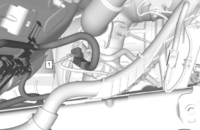
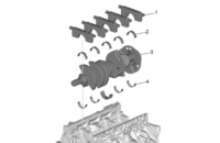
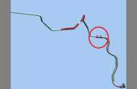
There may be excessive play in the steering or the steering may feel loose on some 2016 Silverado 2500/3500 and Sierra 2500/3500 trucks. There also may be a small power steering fluid leak from the steering gear lash adjuster stud/nut area on top of the steering gear. (Fig. 1)
These conditions may be caused by the pitman shaft adjuster stud unthreading up or out of the cover plate, which can cause excessive lash in the steering gear as well as a small fluid leak past the stud threads. These conditions are not caused by the steering gear pitman shaft adjuster lock nut turning on the adjuster stud. Do not turn the lock nut on the adjuster stud.
TIP: Do not replace the power steering gear for excessive lash, a fluid leak, or a loose play condition without checking the pitman shaft adjuster stud threading.
 Fig. 1
Check the Steering Gear
Check the steering gear through the top of the engine compartment for stud unthreading or fluid leak conditions. It’s not necessary to remove any components to inspect the steering gear. However, if any of the following conditions are found, the wheelhouse liner, wheel, and charge air cooler inlet pipe (if equipped) must be removed to make the repair.
Using a telescoping mirror, examine the steering gear lash adjuster stud and nut:
- The adjuster stud nut (Fig. 2, #2) will not be seated up against the cover plate if the adjuster stud (Fig. 2, #1) has become unthreaded.
- The adjuster stud can easily be turned in or out by hand using an Allen wrench.
- Oil residue may be seen leaking past the stud onto the cover plate.
 Fig. 2
If the pitman shaft adjuster stud has unthreaded from the cover, threadlocker should be applied on the stud threads.
Apply Threadlocker
With the steering wheel centered so the wheels are pointed straight ahead, remove the left front wheel and wheelhouse liner to access the steering gear. Also remove the charger air cooler inlet pipe (if equipped).
Use a marker or scribe to mark the adjuster stud in relation to the adjuster stud nut. (Fig. 3, #1) Next, loosen the adjuster stud (turning counter-clockwise) with an Allen wrench until it is fully backed off. Typically, two threads will be shown. (Fig. 3, #2)
TIP: Do not turn the steering gear pitman shaft lash adjuster nut relative to the stud. Only loosen the stud.
 Fig. 3
With the threads exposed, spray brake cleaner solvent on the stud threads to remove all oil residue. Use compressed air to blow away any remaining debris and the brake cleaner from the stud area.
Apply a thick layer of blue threadlocker around the adjuster stud threads and tighten the adjuster stud (turning clockwise) until the lock nut bottoms out on the cover plate. (Fig. 4, #2) Do not hold the nut while tightening the adjuster stud. If the relation of the adjuster stud and nut (Fig. 4, #1) is changed, the adjuster could seat at the incorrect depth, which would change the lash adjustment of the steering gear.
 Fig. 4
Once the threadlocker is applied, use a torque wrench with a crow’s foot and the Allen wrench to turn the adjuster stud and nut simultaneously. (Fig. 5) Torque the nut to 68 lb.-ft. (92 Nm).
Be sure to keep the adjuster stud and nut in alignment with the mark or scribe. If the stud and nut are not in alignment, slightly loosen the nut to realign the marks and then re-torque the nut.
 Fig. 5
Allow the threadlocker to cure for approximately four hours. Install the charge air cooler pipe (if equipped), and the left front wheelhouse liner and wheel. The vehicle can be removed from the hoist while the threadlocker cures.
Active Hydraulic Assist System
The Active Hydraulic Assist (AHA) system (RPO NV8) is an updated recirculating ball hydraulic power steering system that allows for some of the performance benefits of electric power steering, such as variable effort steering, active return to center, active damping, and lead/pull compensation.
On trucks with the Active Hydraulic Assist system, it will be necessary to:
- Program the Power Steering Control Module with the latest calibrations available in TIS2Web
- Perform the Steering Angle Centering procedure using GDS2. Refer to the appropriate Service Information.
- Perform the Power Steering Pressure Sensor Learn procedure using GDS2. Refer to the appropriate Service Information.
Test drive the vehicle to verify the steering condition has been corrected, the steering wheel is level, and the Steering Wheel Angle parameter is zero degrees (+/-3 degrees) while driving the truck on a flat, level, straight road at approximately 25 mph.
For trucks without the Active Hydraulic Assist System, test drive the vehicle to verify the steering condition has been corrected.
For additional information on the steering gear repair, refer to Bulletin #18-NA-280.
– Thanks to Jamey Houck