Smart motors, switches, and sensors that use Local Interconnect Network (LIN) buses can be found on many 2014-2020 GM passenger cars and trucks. The LIN bus consists of a single wire and is used to exchange information between one master control module (such as an ECM, BCM, etc.) and one or more slave/smart device(s), such as switches, sensors, motors, etc. The LIN bus is relatively simple and exchanges data at a slower rate than other GMLAN buses.
LIN buses are not wired to the DLC, so the scan tool does not communicate directly on a LIN bus. The scan tool will communicate with the master control module of the LIN bus in order to command outputs or read parameters from the slave/smart device(s). If serial data communication is lost between any of the LIN devices on the LIN bus network, the master control module will set a no communication code against the non-communicating LIN device.
Each component on the LIN bus (master and any slave devices) will send out approximately 11-12 volts and then toggle that voltage low when communicating. (Fig. 8) Because the LIN bus voltage ranges between 12 volts and 1 volt, it’s important to have proper battery voltage while performing diagnostics. Install the EL-50313 Midtronics GR8 Battery Tester/Charger or equivalent on the vehicle while diagnosing a LIN bus to avoid a false reading. When a LIN bus is at rest or not communicating, it will read approximately 11–12 volts.
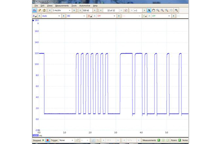 Fig. 8
In most cases, when the ignition is turned on, the master control module will wake up the slave device(s) via the LIN bus. If the slave device does not wake up, the master control module will set a DTC for that device and will continue to try and wake up the slave device, which can be seen by the toggling voltage on the LIN bus.
However, in some cases, the slave device will wake up the master control module. For example, the door ajar switch is hard-wired to the driver’s window motor. The driver’s window motor has a LIN bus to the BCM. When the driver’s door is opened, the ajar switch closes, signaling to the driver’s window motor to send a LIN message to the BCM. The message wakes up the BCM and it communicates to the vehicle that the driver’s door is open. As result, the BCM will turn on the interior dome lights and start waking up other modules.
Diagnostic Tips
Here are a few diagnostic tips for the LIN bus circuit. The LIN bus schematic is used as an example in some of the tips. (Fig. 9) Always follow the appropriate diagnostics in the Service Information.
- If a LIN bus has more than one slave device, check to see if the other devices are working. Looking at the schematic, if the customer’s concern was that the rear wiper was not operating, check to see if the rear power windows operate. This can help in narrowing down the area of concern.
- The LIN bus is a single wire and many faults are basic failures, such as opens, high resistance, shorts to ground/power, poor terminal drag, or connectors not fully seated. Use the proper terminal test probes to inspect for these types of failures.
- Testing/monitoring the voltage of the LIN bus can help determine what type of failure may have occurred.
- Check the output voltage from the master control module: With the master control module connected, disconnect the slave device and turn on the ignition. At the slave device, inspect for the toggling voltage from the master control module on the LIN bus. If using the EL-50772 Insulation Multimeter set to “peak” min/max, the voltages will be approximately 12 volts max and 1 volt min. If the voltage is present but not toggling, it could indicate a short to power. If the voltage is not present, it could indicate an open or short to ground.
TIP: Certain types of shorts on a LIN bus circuit can cause the module to shut down and stop outputting the 11–12 volts until the fault is no longer present and the ignition/power is cycled or DTCs are cleared.
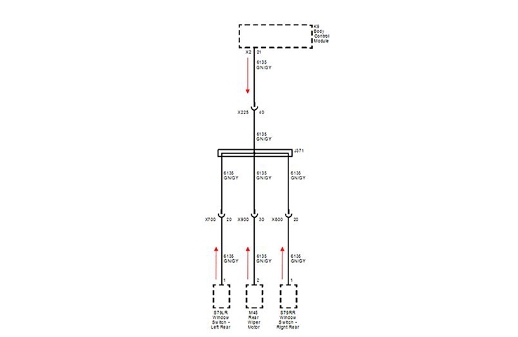 Fig. 9
- Check the output voltage from the slave device(s). With the slave device in question plugged in, disconnect the master control module and all other slave device(s) on the same LIN bus. At the master control module, check the output voltage from the slave device, which will be a steady 11–12 volts. There are a few things to keep in mind when testing the output voltage from the slave devices:
-
- Most slave devices have a hot at all times feed and no switched ignition inputs. In these cases, the ignition does not need to be turned on to test for the output voltage. Always check the wiring diagram for the slave device to determine if it has power at all times or if it has a switched ignition. If it has a switched ignition feed, when the master control module is unplugged, the slave device may not be powered on. In these cases, the slave device will need to have power applied to the switched ignition input before testing.
- When testing the LIN bus output voltage from a slave device, which has a switched ignition, some devices will only have the steady 11–12 volts output for a few seconds before it will drop to 0 volts. This is because the testing is done with the master control module disconnected and, when the slave device does not establish communication from the master control module, it can shut down the LIN bus output voltage.
- If there is more than one slave device, keep in mind that each slave device is sending out an output voltage. In these cases, the other slave device(s) will need to be disconnected along with the master control module before checking the output voltage from the slave device in question.
If no voltage is found coming from the slave device, it could indicate poor terminal tension at the LIN bus terminal, the slave device was not powered on (missing power or ground), or the slave device itself may be at fault.
If the voltage is present, check that the correct part number slave device is installed. Slave device part numbers change from year to year yet the different devices may look similar.
– Thanks to Jim Will
Updated August 8, 2019