
As the technology in new vehicles continues to evolve and expand, more electrical bandwidth and connectivity has become necessary to ensure all the data-driven features can operate efficiently together within the overall vehicle network. The Next Generation Digital Vehicle Platform, GM’s all-new electronic platform, will be used to help power the next generation of GM models and systems, including electric vehicles, active safety systems, infotainment systems, and a variety of connectivity features. (Fig. 1) The new platform will go into production later this year with the debuts of the new 2020 Chevrolet Corvette and Cadillac CT5 and CT4.
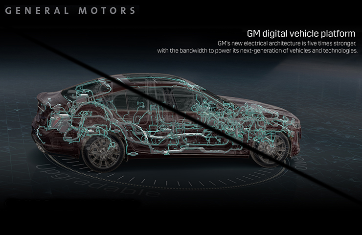 Fig. 1
The Next Generation Digital Vehicle Platform powers a new electronic system that is capable of managing up to 4.5 terabytes of data processing power per hour, which is a fivefold increase in capability over the current Global A electrical architecture. The new architecture provides more rapid communications within the vehicle itself as well as to outside sources with Ethernet connections of 100Mbs, 1Gpbs and 10Gbps.
The system features the Controller Area Network with Flexible Data-Rate (CAN FD) protocol, which supports improved data communication and faster programming by transmitting and receiving data at a higher maximum bit rate. A faster bit-rate allows more data to fit into a single message, reducing the need for more networks (and additional wiring) in a vehicle, which also reduces weight and increases performance.
CAN Communication
The Next Generation Digital Vehicle Platform can incorporate up to nine high-speed CAN buses. Low-speed GMLAN and MOST are not used.
Programming and scan tool data information is provided using CAN buses 6 and 7, which only run between the DLC and the Serial Data Gateway Module, and are used by GDS 2 to provide system data from the other CAN networks. This design isolates the remaining buses to secure those networks and provide enhanced intrusion detection incorporated at the architectural level.
The powertrain CAN bus communicates over a dedicated circuit but the other CAN buses use a wake-up message from the Serial Data Gateway Module, which can be tailored to wake up individual modules when needed. The Serial Data Gateway Module is updated first during programming and then any other modules are programmed through the Serial Data Gateway Module.
TIP: Programming is now done with all doors closed and the ignition off. With this new process, the Serial Data Gateway Module can wake up a specific module for programming with no other information on the bus, which also promotes faster programming.
In addition, there are several Diagnostic Trouble Codes (DTC) that have changed from the previous Global Architecture (Global A) to the new Next Generation Digital Vehicle Platform.
GDS2 Support
The GDS2 Core 21.1.07400 software update added Next Generation Digital Vehicle Platform capability.
For communication diagnostics, the Serial Data Gateway Module will periodically poll for module communication across all sub-networks. When a non-communication event is detected, the information is recorded and presented in a table under Vehicle Diagnostics > Vehicle Communication Diagnostics > Network Communication Event Results.
The event results include up to 50 records (up to 9 records per CAN1 or CAN2 and up to 8 records per CAN3, CAN4, CAN5, or CAN8). Select the CAN Bus Records tab to view the recorded data. It shows the CAN bus that encountered an event and the number of times the fault occurred (up to a maximum of 255). In addition, the timestamps list the time of the first failure — the larger the number, the more recent the event — and the last failure, which is displayed when the event is no longer present. The Delta column shows the difference between current time and the first failure, with a smaller number indicating a more recent event. (Fig. 2)
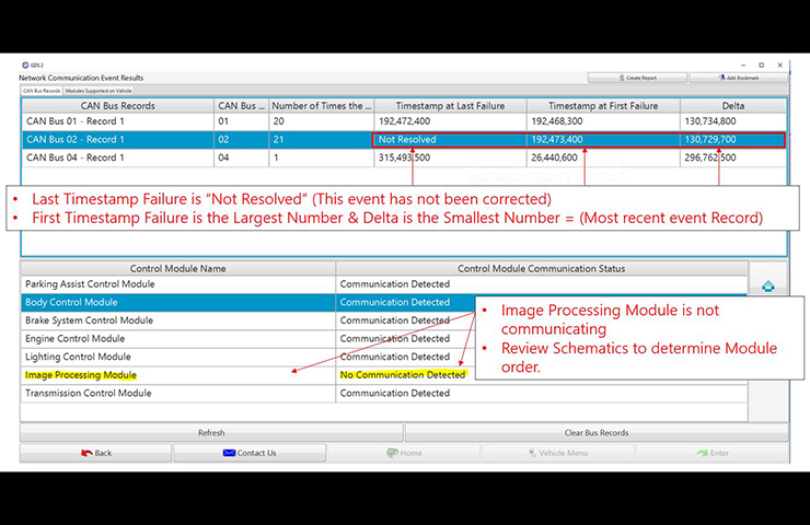 Fig. 2
Under the record data, defined control modules are listed by name while undefined modules will display their diagnostic ID. Communication status will be listed as Communication Detected or No Communication Detected. (Fig. 3) Additional status information will be added in future model years.
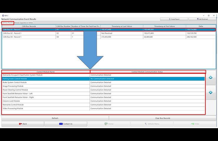 Fig. 3
The “Refresh” button at the bottom of the table can be used to request new data on demand. When events are no longer occurring, the event records can be cleared by selecting the “Clear Bus Records” button.
Under the Modules Supported on Vehicle tab, the control modules for the vehicle are identified along with the CAN bus number connected to each module. Modules connected to more than one bus will be listed in multiple rows. (Fig. 4)
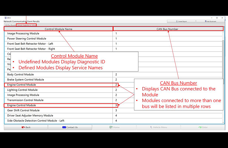 Fig. 4
The network communication status of the control modules on each bus also can be viewed by selecting Vehicle Diagnostics > Vehicle Communication Diagnostics > Network Communication Status. When checking status, a request is sent to all modules on a targeted sub-network. Select the Refresh button at the top of the table to run the status procedure additional times. (Fig. 5)
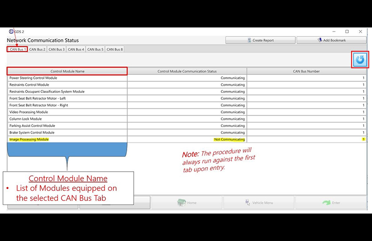 Fig. 5
The GDS2 software update is available by selecting the GDS2 icon in TIS2Web. For assistance, contact the Techline Customer Support Center (TCSC) at 1-800-828-6860 (English) or 1-800-503-3222 (French).
– Thanks to Chris Henley


This is a feature currently in testing that will be released in the future. We’ll publish an explanation when it’s released into production.
I noticed a “TYPE” column was added to the GDS2 Vehicle DTC Information Report.
Is this something related to Next Generation Digital Vehicle Platform.
what study material is available for this ?
hi there, my question is, is there a very good reading training material for this new communication system? and previous communication systems? thank you