
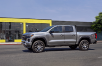
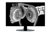
The Surround Vision camera system (RPO UV2) available on a variety of GM models displays an overhead view of the area surrounding the vehicle, along with front or rear camera views, on the infotainment screen. (Fig. 16) The front camera is in the grille or near the front emblem of the vehicle, the side cameras are on the bottom of the outside rearview mirrors, and the rear camera is above the license plate.
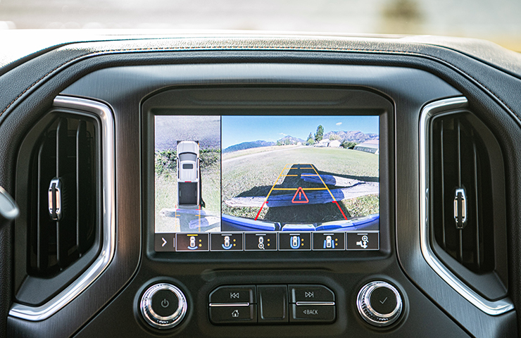 Fig. 16
The Surround Vision system consists of the following components:
- B87 Rear View Camera
- B174G Front View Camera – Grille
- K157 Video Processing Control Module
- A11 Radio OR K74 Human Machine Interface Module
- B225L Side View Camera – Left
- B225R Side View Camera – Right
- X20 Memory Card Receptacle
System Operation
When the vehicle is traveling at speeds slower than 6 mph (10kph) the Video Processing Control Module will power up the cameras and send a video signal to the radio or human machine interface module. (Fig. 17)
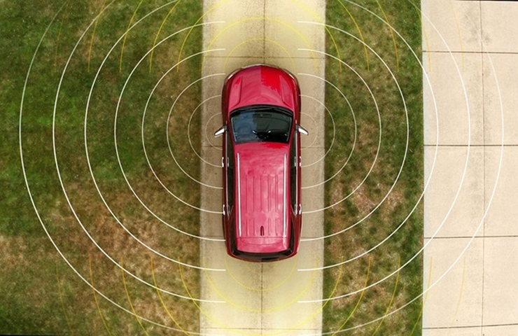 Fig. 17
The Video Processing Control Module sends voltage and a constant ground to power the cameras. Video signal + and video signal – circuits carry the video image from the cameras to the Video Processing Control Module for processing, which will then send the processed image output to infotainment system by video signal + and video signal – circuits. All the video signal circuits are twisted and shielded to prevent any interference that may lead to a loss of video signal resolution and cause a degraded video image. These circuits must not be spliced/removed from shielding or image degradation may occur.
The Video Processing Control Module receives CAN information from the Rear Park Assist Object Detection Module and steering wheel angle from the Body Control Module while the vehicle is in Reverse.
Diagnostics
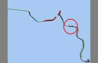
During diagnosis of the Surround Vision system, there may be several DTCs set relating to wiring issues with video signal from the cameras to the Video Processing Control Module or from the Video Processing Control Module to the radio. Refer to the following chart for some common signal concerns that may appear as a blue screen or a distorted image on the infotainment screen. (Fig. 18)
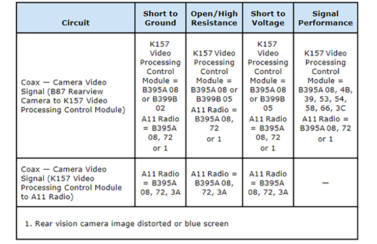 Fig. 18
An open in the shield of the video signal circuit also can cause a distorted screen.
If the Video Processing Control Module cannot calibrate all cameras, the camera image may be displayed without projected path lines.
Also, an open in the backup lamp control circuit, defective backup lamps, or incorrect/aftermarket backup lamps may cause erratic circuit behavior, such as unwanted voltage on a circuit when vehicle is no longer in Reverse. The camera image display remaining active after the vehicle is shifted out of Reverse also may indicate possible backup lamp control circuit issues.
Terminal Fretting
Some intermittent conditions can be caused by wire terminal fretting corrosion, which is a build-up of insulating, oxidized wear debris that can form when there is a small motion between electrical contacts. Fretting corrosion can be difficult to see but it looks like small, dark smudges on the contact surface of the terminals.
If the condition is intermittent or cannot be duplicated, disconnect the connectors and add dielectric grease or lubricant (Nyogel 760G or equivalent, meeting GM specification 9986087) to both sides of the terminals. The dielectric grease should correct any high resistance conditions that are due to terminal fretting corrosion.
Coax Cable Testing
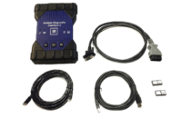
The EL-52552 COAX FAKRA Cable Adapter Kit (Fig. 19) can help in diagnosing a variety of coax cables, including Wi-Fi, cameras, and antenna cables.
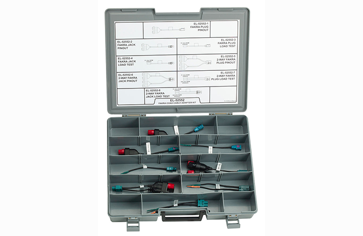 Fig. 19
The EL-52552 Kit covers all known cable configurations equipped with FAKRA connectors. Using the adapters in the kit allow a connection to one end of the coax cable (with resistors) connector and having to only probe the other connector end, unlike the current method of end-to-end testing by connecting three or four DVOM test leads together. Banana jacks enable the use of the terminal adapter kit.
The kit can be used to test for voltage to components as well as to test the coax cables.
TIP: Before testing the coax cable, check the cable’s exterior for being pinched, cut, damaged, or having loose connections at the components, all of which can cause reception issues.
Video Processing Control Module Calibration
If the Video Processing Control Module is not calibrated adequately, it will display an hour-glass icon on the infotainment screen. Once calibration is attained, the hour-glass will automatically disappear.
The calibration is performed automatically by the Video Processing Control Module and is needed to have the Video Processing Control Module learn new cameras and their positions.
Any time a cameras is replaced on the Surround Vision Camera System, the camera image needs to be calibrated to the system. The Video Processing Control Module performs the calibration during its power up and initialization sequence at each ignition cycle in order to maximize the Surround Vision image quality.
If the Video Processing Control Module is replaced, the new module will have built-in default values for camera learn. However, the Video Processing Control Module will automatically calibrate in order adapt to the vehicle.
To allow the Video Processing Control Module to complete calibration, drive the vehicle. To reduce the time needed to complete the calibration, the vehicle should be driven on a reasonably flat and straight surface for at least 0.3 miles (0.5 km) at a speed of 6–19 mph (10–30 km/h).
– Thanks to Russ Gilbert


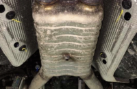


Will there be a camera coaxial cable service kit (similar to the antenna coaxial cable kits) in the future for these vehicles? Currently have an employee’s ’19 GMC AT4 with intermittent grille camera operation. Finally pulled the grille for inspection to find the center conductor on the coaxial cable was folded over, both ends damaged, replacement of both cables necessary. From what it looks like (and was told by TAC), I have to order a vehicle body harness & cut the coaxial cable out & install it in the problem vehicle.
The EL-52552 kit was shipped as an essential tool in 2018 to all USA and Canadian dealers.
Is the coax test kit an essential tool?